Classic Coil is happy to offer engineering assistance as a service to our clients. For qualified projects, we will make prototypes at a minimum charge plus any out of pocket tooling costs.
Classic Coil will work with you through each step of the design process. Our Engineering staff stand ready to work with you to optimize you coil design for functionality and low cost.
Engineering Assistance starts with understanding your product’s environment through to first production runs. We follow Advanced Product Quality Planning (APQP) guidelines for product development.
Please use the links below to learn more about Classic Coil’s Engineering Assistance process. When your ready to get started, click here to fill out our request form and a Classic Coil engineering representative will contact you.
Bobbin Design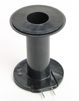 If your design has room for a bobbin and your annual demand is over 300 coils/yr, a bobbin will save you time and money.
Consider using a stock bobbin for initial qualification. Most stock prototype bobbins are nylon. Customer specified material can often be used in the same mold. See note below for reserving and additional .150 inches in length to design the bobbin for automated winding and welding.
Classic Coil’s engineering staff will help you select a stock bobbin. Ready to get started? Contact us to specify your basic coil foot print. Remember to reserving an additional .150 inches in length to design the bobbin for automated winding and welding.
Production Bobbin Considerations:
- Most glass filled bobbin flanges should be at least .030” thick
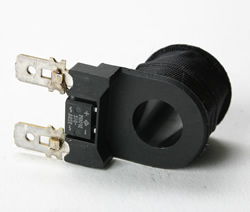
- Annual volume has the potential to exceed 5000. Add .100-.120” to the top flange and .030” to the bottom. This added footprint will allow for bobbin to carry terminals (thus eliminating the costly manual soldering operations- see discussion on Molded Coils.) The added height will also accommodate automated winding machines
- Bobbin material depends upon UL and environmental considerations – see encapsulant area for UL material selection
- Bobbin terminal slot can be designed to take spade terminals that match the mating female connector or accept lead wire to be welded
- Spacing between terminals- UL dependent
- Bobbin design should accommodate diodes, rectifiers or fuses
- Moisture barriers may need to be designed into the bobbin
- UL Considerations for bobbins not to be overmolded
UL Considerations for bobbins not to be overmolded*
| UL Class |
Magnet wire |
Bobbin/tube material |
| F |
MW 26/ MW 24(180C) |
Rynite series 415HP, FR 515, FR 530, FR530L, Nomex 410, Zytel |
| F |
MW80 (150C) |
Rynite FR 530, Nomex |
| H |
MW 35, MW 74(200C) |
Aramid Paper, Nomex |
|
*For coils that will be over molded, see Encapsulate Decisions
Metal Bobbins for Cores, Rotors , LVDT, RVDT
- must be insulated between the bobbin, rotor, and magnet wire
- For bobbin-Kapton tape provides the insulation
- For rotors and where space is limited-use 3M Scotchcast powder resin. Contact Classic Coil Engineering for help in specifying electrostatic coatin
Magnet Wire & Lead Wire SelectionMagnet Wire Selection
Magnet wire is insulated with an enamel coating to allow coil windings to touch each other without conducting electricity between layers. Various enamels have different temperature ratings:
- UL consideration- 155C (MW 80), 180C (MW 77) 200 C (MW 35 or 74) and 220C (MW 16). Temperature refer to 20,000 hours of continuous duty operations per ASTM D2307
- 5 AWG to 48 AWG
- Enamel comes in Single coat – most common for wire sizes finer than 12 or Heavy coat for stress conditions
- Bondable coating can be added to the wire where no bobbin will be used
- Litz Wire- special coating for high frequency conditions
- 200C and 220C require additional manual stripping the ends for soldering
Lead Wire or Terminal Selection:
- UL Considerations – Temperature classifications
- Terminals in bobbin helps in design for automation
- Terminal bobbin can also be used with lead wire
- Operating Moisture and temperature requirements
- See Engineering department when considering Teflon leads in moisture environment for encapsulated coil
Magnetic Path Components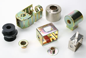
Frames, Yokes, Housings, Cores and Flux washers are used to manage the magnetic field created by the coil.
- C or D shaped frames
- C frames reduce the power curve by approximately 10% of a D Frame
- C frame offers benefits when overmolding and coil contains electronics, e.g. Diodes, varistors, full wave bridge, fuse, TVS (Transit Voltage Suppressors), etc.
- D frame, when external to coil, provide indexing avenues. Internal to coil provide a ground post for a din version, Conduit or lead wire
- For wide temperature fluctuation or increased water resistance, put the frame on the outside of molded coil
- Flux washers- plated washers that go between the frame and bobbin flange to guide the magnetic field down the ID of the coil
- Stamped Steel housing- helps with conduit applications, improves power (controls more of the magnet field than the D frame), and provides a container for small volume epoxy type coils
- Machined housing- low volume choice; allows for smaller footprint of coil by using less copper but higher quality magnetic steel. Common choice for Aerospace solenoids, LVDT, and sensors
Encapsulant Decisions
| UL Class |
Magnet wire |
Bobbin |
Encapsulant |
Comments |
| B |
MW 80 (155C) |
ZYTEL 70G33L |
ZYTEL 70G33L |
MW35 wire allowed |
| B |
MW 80 (155C) |
ZYTEL 70G33L |
Nor cast 3259 |
Liquid epoxy |
| B |
MW 80 (155C) |
ZYTEL 70G33L |
Farboset 1115 |
Epoxy |
| B |
MW 80 (155C) |
ZYTEL 70G33L |
Fiberite E8833 |
Epoxy & glass |
| B and F |
MW 80 (155C) |
RYNITE FR 530 |
RYNITE 415HP |
– |
| F |
MW 26(180C) |
Ryton R 4 |
Ryton R 4 |
– |
| F |
MW 26(180C) |
Ryton R 4 |
Farboset 1115 |
– |
| F |
MW 80 (155C) |
RYNITE FR 530 |
RYNITE 415HP |
– |
| F |
MW 26(180C) |
ZYTEL 70G33L |
ZYTEL 70G33L |
MW35 wire allowed |
| F |
MW 26(180C) |
ZYTEL 70G33L |
Farboset 1115 |
– |
| H |
MW 35,74 (200C) |
Aramid paper |
Farboset 1115 |
– |
| H |
MW 35,74 (200C) |
Aramid paper |
Nor cast 3259 |
– |
| H |
MW 35,74 (200C) |
Ryton R 4 |
Ryton R4 |
– |
| H |
MW 35,74 (200C) |
Ryton R 4 |
Farboset 1115 |
– |
| H |
MW 35,74 (200C) |
Ryton R 4 |
Fiberite E8833 |
– |
| H |
MW 35, 74 (200C) |
RYNITE 5220 |
RYNITE 5220 |
– |
|
|
 Tooling:
Our 50 years of accomplishments insure consistent results. Costs are very dependent upon cavity configuration.
- The RYNITE, Ryton and ZYTEL are thermoplastics with faster molding press time
- Farboset and Fiberite are Thermoset materials
- Norcast 3259, 2 part liquid epoxy, is the slowest of the Encapsulant processes The material requires vacuum impregnating and oven time
Other Considerations:
- Heat dissipation- Farboset 1115 dissipates heat approximately 3 times faster than most engineered thermoplastics plastics
- Coils using magnet wire finer than 38 AWG benefit from using the gentle pressures used in thermoset transfer molding
- Special design techniques are required Injection molding coils with integrated electronics( diodes, varistors, TVS). These components need to be protected from high pressure
- Overmolded water resistant coils use design techniques to minimize weeping at lead/ terminal area
- Explosion proof coils are designed with exacting verification that all air has been pushed out
- Our thermoset, Farboset 1115, proprietary, will mold thinner wall sections than most thermo plastics
CAD Component FilesGeneric CAD files are presented to reduce design time. They need to be altered for a particular application.